LCD Display
The HD4480 is a popular chipset used in all manner of small LCD displays. This page documents how to wire one up to the 6502 processor bus and some code to control it.
Bus interfacing
The electrical interface to the HD4480 is fairly 6502 friendly. There are 8
parallel data lines D[0…7] which are set by the HD4480 when reading data
from the display and read by the HD4480 when writing. There is a single register
select (RS) line which is low to indicate access to the control register(s) and
high to read/write data from the display itself. There is the usual R/W
line to indicate whether data is being read from or written to the display and
there is a display enable (E) line which is taken high to indicate to the
display that the values on the control/data lines are intended for it.
Reading data from the display is a relatively unsurprising affair:
- Set RS to indicate whether one is reading the busy flag/RAM address or reading data from the display.
- Set R/
Whigh. - Set E high.
- Read byte from D[0…7].
- Set E low.
Similarly, writing data to the display is straightforward:
- Set RS to indicate whether one is writing the control register or sending data.
- Set R/
Wlow. - Set byte on D[0…7].
- Set E high.
- Set E low.
This is very similar to the way the 6502 performs reads and writes. The subtlety
is in how the E signal is generated. If it is by some address line decoding,
which it is on Búri, then the E signal will change during φ1 which is
before the R/W and data lines are stable. This is easily fixed
by making E conditional on φ2 being high.
All of the displays I have can run at 2MHz and so no additional logic is needed if the 6502 is running at 2MHz or slower. Thankfully Búri is a 2MHz machine by design so I can stop here. I may need to re-visit the bus adapter at a later date if I move Búri to 4MHz or greater.

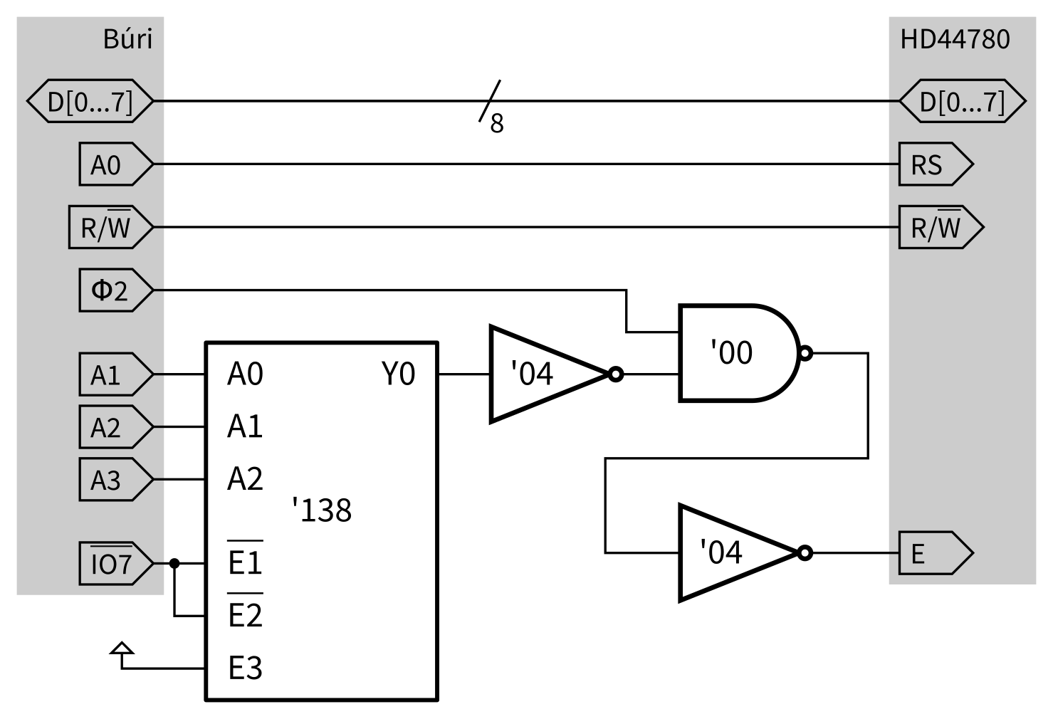
The complete bus logic is shown above. Here I’ve used a 74138 3-to-8 decoder to
select out the bottom two bytes from I/O area 7. (Búri will take IO7
low when bytes in the range $DFF0–$DFFF are accessed.) I use A0 as
register select and feed A[1…3] into the ‘138. I use a single 7400 NAND
gate to condition E on φ2 and a couple of 7404 NOT gates to flip some
signals around.
Testing
According to the datasheet, the display is controlled by writing to register 0 (which is at $DFF0 using the circuit above) and data is written to register 1 (exposed at $DFF1). The control bytes I need to send are:
- $38: enable 8-bit mode, 2 line display and 5×8 font.
- $0D: switch display on and have “blinking block”-style cursor.
- $01: clear display and move cursor to home position.
With the Búri OS, these steps can be performed via the poke command:
*poke dff0 38
*poke dff0 0d
*poke dff0 01
Writing a message can be performed by writing character codes one at a time to $DFF1:
*poke dff1 48
*poke dff1 65
*poke dff1 6c
*poke dff1 6c
*poke dff1 6f
*poke dff1 21
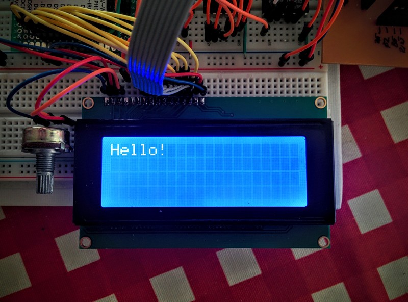
With the display connected to Búri, this is what I got after typing those commands:

Software
The LCD driver software is written in assembly. Most of the code is actually a series of macros to make writing routines more convenient. For example, the most basic functionality is writing data to and reading data from the display. We need to be careful to make sure the display is not busy before writing or reading data.
Basic I/O
Let’s start with some basic macros to read and write to the display.
; Location of the LCD registers in memory
LCD_R0 = $DFF0
LCD_R1 = LCD_R0 + 1

; Macro to wait for display to be ready. Sets A to the current address which
; will be written to by send_cmd.
.macro wait_rdy
    .local loop
loop:
    lda LCD_R0          ; read register 0
    bmi loop            ; loop if busy flag (bit 7) set
.endmacro

; Macro to write value in A to display. Reg should be LCD_R0 or LCD_R1 to
; determine if value is written to control or data register.
.macro write_dpy Reg
    pha                 ; save A on stack
    wait_rdy            ; wait for display (corrupts A)
    pla                 ; restore A
    sta Reg             ; write A
.endmacro

; Macro to read value into A from display. Reg should be LCD_R0 or LCD_R1 to
; determine if value is read from control or data register.
.macro read_dpy Reg
    wait_rdy            ; wait for display (corrupts A)
    lda Reg             ; read A
.endmacro
Now we can define the various parameters of our display. My 20×4 display is arranged with a slightly odd ordering of lines with respect to display addresses. Rather than taking up space with code to compute the line offsets, it’s more space-efficient to just code a small lookup table:
LINE_LEN   = 20       ; Length of a single line (characters)
LINE_COUNT = 4        ; Number of lines of text

; Lookup table for addresses corresponding to start of lines in display RAM.
.export line_addrs
line_addrs:
    .byte #0, #64, #20, #84
Cursor positioning
With the lookup table it’s easy enough to write a macro to calculate a display address from the corresponding x- and y-co-ordinates.
; Interpret X as characters from right (0-based) and Y as lines from top
; (0-based). Set A to the corresponding display address. If X and Y are outside
; of the defined area, the result is undefined.
.macro pos_to_dpy_addr
    txa                 ; set A = X to begin with
    clc
    adc line_addrs, Y   ; A += offset to start of line Y
.endmacro
We can use our macros to write a routine which sets the current cursor position based on the X and Y registers.
; Interpret X as characters from right (0-based) and Y as lines from top
; (0-based). Move the display cursor to this position. A is set to the value
; currently on the display at that position. If X and Y are outside of the
; defined area, the result is undefined.
.proc move_cursor
    pos_to_dpy_addr     ; X, Y => address stored in A
    ora #$80            ; set high bit
    write_dpy LCD_R0    ; write command byte to display
    read_dpy LCD_R1     ; read contents
    rts
.endproc
Our OS will use the two zeropage locations lcdx and lcdy to store the
current cursor position. We can use these to write a “move right” routine.
.zeropage

; Reserve two bytes of zero page for LCD cursor.
lcdx: .res 1
lcdy: .res 1

.code

; Move the cursor to the right.
.proc move_cursor_right
    pha                 ; save registers on stack
    phx
    phy

    ldx lcdx            ; load current position into X and Y
    ldy lcdy

    inx                 ; increment X
    cpx #LINE_LEN       ; compare X to line length
    bcc set_pos         ; X < line length, all done

    ldx #0              ; move to next line
    iny
    cpy #LINE_COUNT     ; compare Y to number of lines
    bcc set_pos         ; Y < number of lines, all done

    ldy #0              ; reset back to upper left, see comment below

set_pos:
    stx lcdx            ; record new X
    sty lcdy            ; record new Y
    jsr move_cursor     ; move display cursor

exit:
    pla                 ; restore registers from stack
    plx
    ply
    rts
.endproc
Our move right routine simple wraps the cursor at the bottom-right back to the
top-left. In the actual implementation, Y is set to LINE_COUNT-1 and the
display is scrolled up by copying data from lower lines to upper lines. The
scroll code isn’t very interesting. Similar move_cursor_left,
move_cursor_up and move_cursor_down routines can be written without too
much difficulty.
Writing characters to the display
With these support routines in place, writing a simple putc implementation
is fairly straightforward.
; Write ASCII character in A to the LCD screen and, if printable advance cursor
; to the right.
.export lcd_putc
.proc lcd_putc
    cmp #$20              ; printable chars are >= $20
    bcs printable         ; if A >= $20 it's printable

    cmp #$08              ; is A == ASCII backspace?
    beq backspace

    rts                   ; ignore all other chars (TODO: newline, etc)

backspace:
    jsr move_cursor_left  ; perform backspace...
    rts                   ; ...and return

printable:
    write_dpy LCD_R1      ; write character to display
    jsr move_cursor_right ; advance cursor...
    rts                   ; ...and return
.endproc
This function assumes that the LCD hardware cursor and lcdx, lcdy stay
in sync. We could explicitly set the cursor position before writing the
character but if you start writing directly to the LCD behind the OS’ back, you
deserve what you get!
Adding support for newline and carriage return is simply a case of
checking for ASCII $0A and $0D respectively then calling the appropriate
move_cursor_... routine.