Serial port
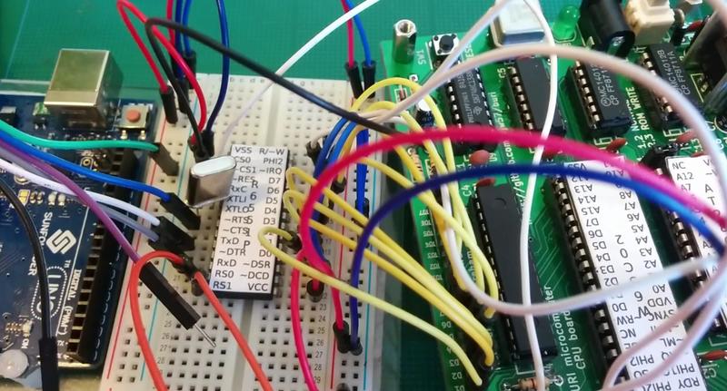
The serial port was the first peripheral I made for Búri. Indeed I first prototyped it as part of Búri itself. The reason for this is that it was the first way Búri could actually be used as a computer. Lacking a keyboard input or a display, the serial port was the only means of interaction and allowed me to play with Búri without having to design additional I/O circuitry.
The serial port was designed to be used in conjunction with a FTDI USB to serial module. This meant it would be very easy to connect the prototype Búri to my laptop for testing. You can see the early serial port interface present in a picture of an early breadboard prototype for Búri.
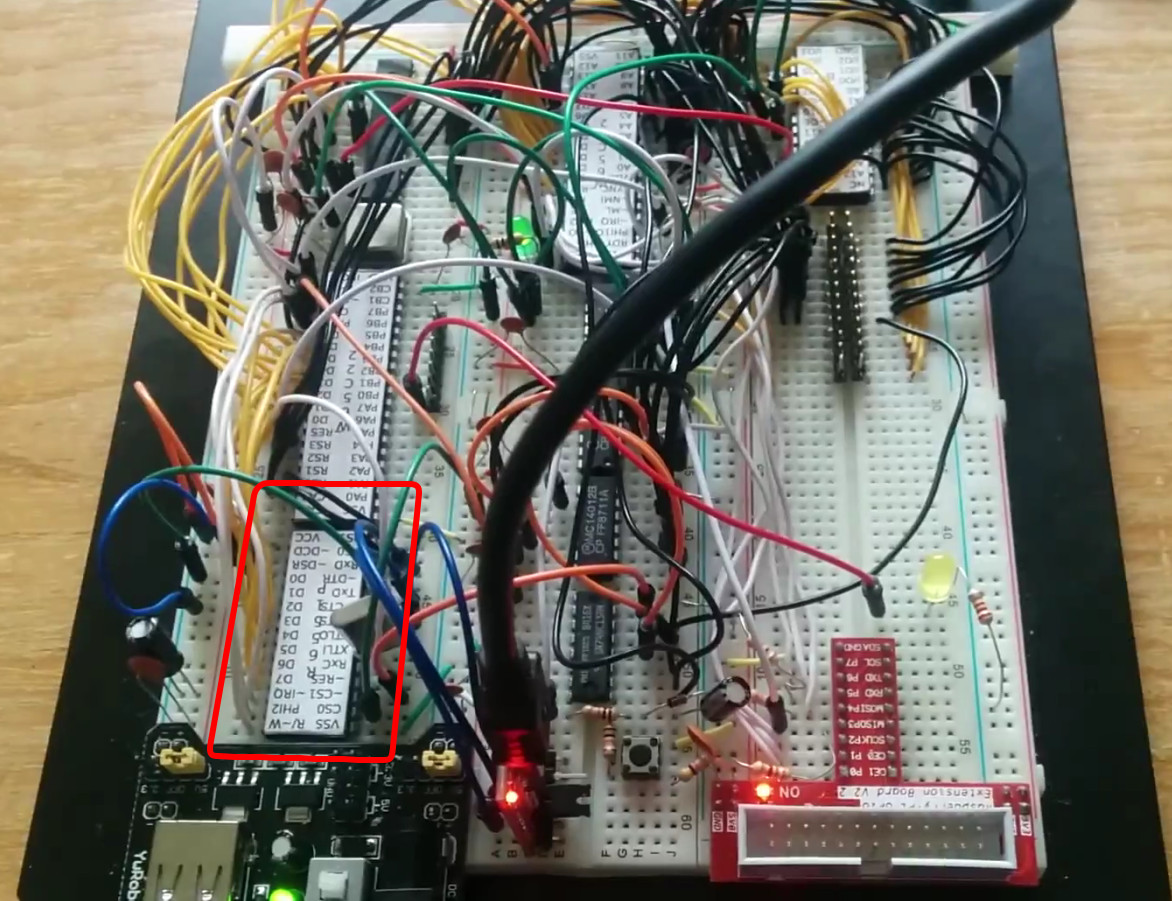
This initial version connected the ACIA CS1 line directly to IO7
with the practical effect of making the ACIA appear as four bytes repeated over
the entirety of I/O area 7. The current module is a little more sophisticated.
Connecting the 6551 to Búri’s bus
The serial port adapter is based around the 6551 chip. This is a chip designed explicitly to be used with the 6502 and so very little circuitry is required to attach it to Búri’s bus.
The 6551 provides all the signals necessary for a full serial port implementation. Only a handful of these signals are needed to communicate with the FTDI module. Let’s first consider the connection of the 6551 to Búri’s bus.
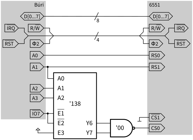
In the adapter, the data and control buses from the CPU are directly connected to the corresponding lines on the 6551. A0 and A1 are used as RS0 and RS1 inputs respectively exposing four contiguous bytes in memory as the 6551 registers.
The IO7 A1, A2 and A3 lines are connected to a 74138 3-to-8 decoder chip.
This decodes eight two-byte areas covering I/O area 7. The top two ranges are
selected by a 7400 NAND gate which outputs logic high when either of the Y6 or
Y7 outputs go low. The reason for using two byte areas means that the same 74138
chip can also be used as part of the LCD display peripheral.
Connecting to the FTDI module
TODO.
Serial port module
In order to save space on breadboards, and to make it easier to wire up the serial port, I wired up a simple serial port module which allows the FTDI module to be directly plugged into the 6551.
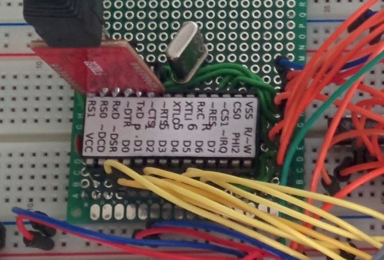
The module itself is quite compact. I plan to add the ‘138 3-to-8 decode chip onto the module and expose the Y[0…5] lines to allow the module to be a generic breakout board for I/O area 7.
Software
We’ve arranged for the ACIA control and data registers to appear as the last four bytes of I/O area 7. We can define some symbols in our assembly code to make referring to the registers by name possible. If one refers to the datasheet you can see that the transmit and data register fullnesses are indicated by bits 3 and 4 in the status register. Let’s also define a couple of masks to keep track of that.
; The linker exports this symbol pointingf to the start of the I/O ranges.
.import __IO_START__

; ACIA1 is at *end* of final IO page.
ACIA1           = __IO_START__ + $70 + $0C
ACIA1_DATA      = ACIA1
ACIA1_STATUS    = ACIA1 + 1
ACIA1_CMD       = ACIA1 + 2
ACIA1_CTRL      = ACIA1 + 3

; ACIA-related constants
ACIA_ST_TDRE = %00010000        ; status: transmit data register empty
ACIA_ST_RDRF = %00001000        ; status: read data register full
Initialisation
Initialising the serial port is straightforward enough. We need only write a couple of values to the control and command registers. Since we’re living in the future, we can just hard-code the fastest baud rate possible. We’ll also be using direct polling rather than interrupts for reasons of simplicity. Again, referring to the datasheet, it’s easy to find the appropriate values.
; srl_init - initialise serial port on ACAI1
.global srl_init
.proc srl_init
        pha

        ; Initialise the serial port
        lda #%00011111          ; 8-bit, 1 stop, 19200 baud
        sta ACIA1_CTRL
        lda #%00001011          ; No parity, enable hw, no interrupts
        sta ACIA1_CMD

        pla
        rts
.endproc
Reading and writing data
Reading and writing are very similar. The general procedure is to wait for the transmit register to be full/receive register to be empty and then write to/read from ACIA_DATA. Conveniently, the 6551 uses 1 to indicate receive register full but uses 1 to indicate transmit register empty. Thus both routines need only wait until the appropriate bit in the status register is 1. The BIT instruction makes this highly convenient. It takes the logical AND of the value in A with that specified in the instruction and sets or clears the zero flag as appropriate. We can therefore sit in a tight loop using BIT and BEQ in both the send and receive routines.
The remainder of the putc and getc routines are very simple, we write A
to ACIA1_DATA or read A from it as appropriate.
; srl_putc - send a character along the serial connection.
;
; On entry, A is the ASCII code of the character to send.
.export srl_putc
.proc srl_putc
        pha                             ; save A on stack

        lda     #ACIA_ST_TDRE           ; load TDRE mask into A
wait_tx_free:
        bit     ACIA1_STATUS            ; is the tx register empty?
        beq     wait_tx_free            ; ... no, loop

        pla                             ; retrieve output char from stack
        sta     ACIA1_DATA              ; write character to tx data reg
        rts                             ; return
.endproc

; srl_getc - wait for the next character from the serial port.
;
; On exit, A is the ASCII code of the character read.
.export srl_getc
.proc srl_getc
        lda     #ACIA_ST_RDRF           ; load RDRF mask into A

wait_rx_full:
        bit     ACIA1_STATUS            ; is the rx register full?
        beq     wait_rx_full            ; ... no, loop

        lda     ACIA1_DATA              ; read character from ACIA
        rts                             ; return
.endproc
The other side
The other side of the connection can be any computer with a USB or a serial
port. I like picocom as a simple serial terminal program. It also supports
sending files over XMODEM which makes it useful when combined with the xrecv
command in the Búri OS.
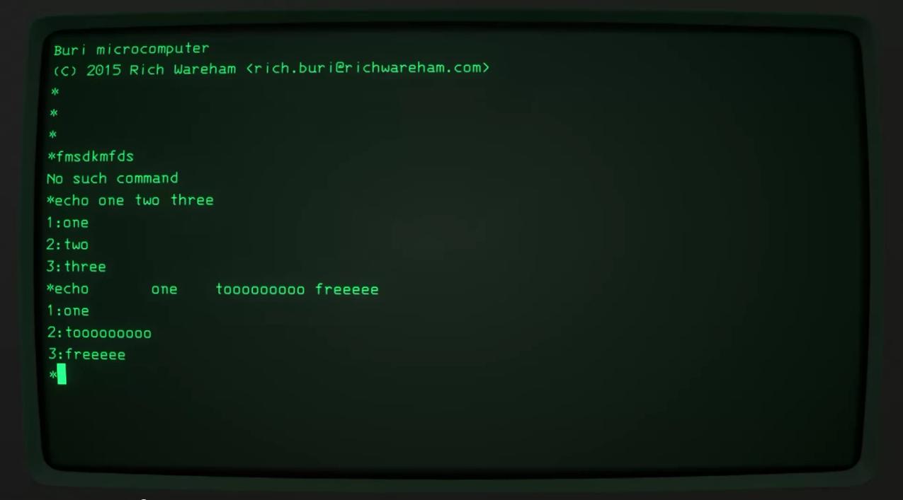
Running picocom and specifying the use of XMODEM as a file transfer program is straightforward in Linux:
$ picocom -b 19200 /dev/ttyUSB0 -s sxThis command specifies that picocom should use a baud rate of 19200, use the
sx program for sending files and that the serial port device is
/dev/ttyUSB0. In the rare event that you have multiple USB-to-serial
adapters plugged into your computer, you may need to increment the 0 in the
device name(!)
I quite like using cool-retro-term as a terminal emulator for this since it gives me the feeling of using a true 1980s computer.